Networking and Communications//
I2C communication
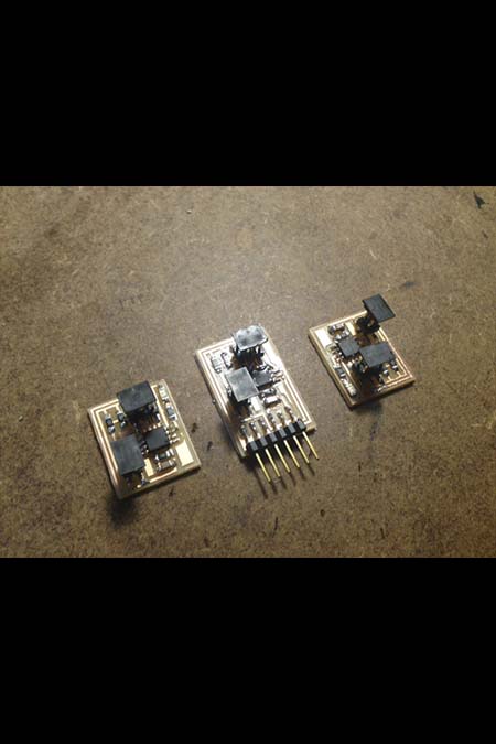
For this week i chose to make 3 boards (one bridge and 2 nodes) to communicate with one another. I decided to work with Neil's boards , a hello.I2C.45.bridge and hello.I2C.45.node .I decided to make I2C communication in one board. I2C protocol works on SCK and SDA. But waht exactly is I2C communication?The Inter-Integrated Circuit bus (I2C) is a patented interface developed by Philips Semiconductors. The I2C bus is a half-duplex, synchronous, multi-master bus requiring two signal wires: data (SDA) and clock (SCL). These lines are pulled high via pull-up resistors and controlled by the hardware via open-drain drivers, giving a wired-AND interface.I decided to work with this since is the right one for my final project and the smart textiles that i want to do. I decide to follow first Neil;s example and then to create a second round of boards for
Eagle software and board design
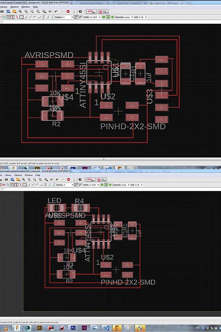
As i decided first to use Neil's board as a prototype i created in eagle all the circuit of the slave and of the bridge circuit. I tried to make it similar to the original design.

Eagle schematics
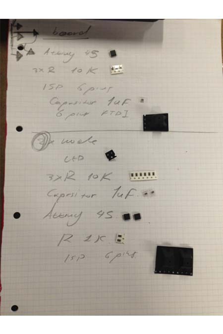
Components
There were a lot of components since i had to mill three boards. The components of the bridge board are attiny 45, 3*Resistors 1o k, ISP 6PINS,capasitor 1uf. The components for the node are : red led, 3* resistors 10k, capasitor 1uf, ISP 6 pins and attiny 45.
Coding 1
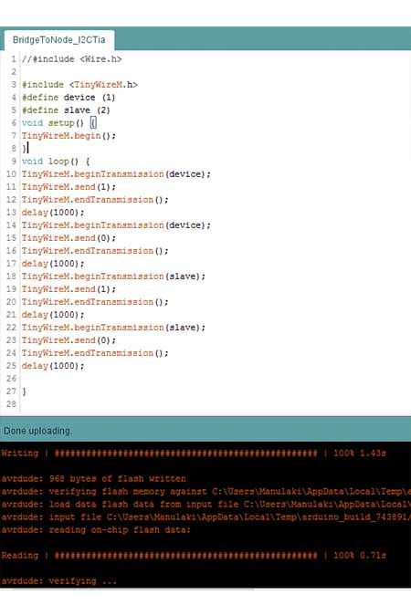
The most tricky thing of this week was coding since i need two kind of codes. One for the bridge board and one for the node. Every NODE board has to have an ID, a number with which the bridge will regognise in which board should send the signal. That why in the begining of the node code i set the #define I2C_SLAVE_ADDR (1) when is about the first node and #define I2C_SLAVE_ADDR (1) when it comes to the second node. The code was taken by a previous fab academist S M Anamul Arefin who documented and organized everything very well. The code of the bridge to node was succesful and the first step was completed.
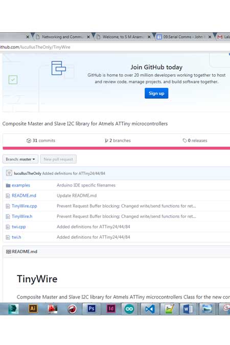
Tinywires.h library
A big obstacle that i faced was tha fact that i did not have the right library that the code is linked to. I had the WIRE library of the arduino installed but unfortunatlly not the one of the attiny 45. I found it in github, downloaded and installed it in arduino libraries.
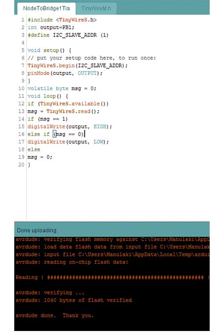
Coding 2
Unfortunatelly, the second try to program the second node did not work. The code was verified but i quess that ther is something wrong probably with the connections of the nodes. Luckily, the first node was programmed as we can see at the picture.
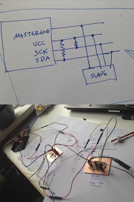
Work in progress
After having tried to make the Neil example work (in the end I had again problem using Arduino as ISP…) I decided to try again communication directly on my final project boards I realized that in the rush of the final days I had forgot the pull-up 10kΩ resistors on my SDA and SCK lines for the I2C (I made some confusions between this and other type of communications, it was not 100% clear to me by the time I had done the schematics and milled the boards). I didn’t have time to make a new board (I will for the final project, the slave needs some modification anyway…) so I tried to solve the problem by connecting the SDA and SCK with the resistors to Vcc directly from the cables… I know, not the most elegant solution, but it was a temporary fix!

Work in progress/coding 1
I started looking into I2C code online to have the ATtiny45 communicate, I was from the beginning redirected to the TinyWire libraries of bHogan. I used his example code of Tiny85_Temp where an AT85 acts as a master reading from another board with a temperature sensor< and combined with another code where an AT85 is acting as a slave and an Arduino with an I2C scanner as a master, I just had to modify the Wire.h command into the TinyWire.h commands…
Work in progress/coding 2
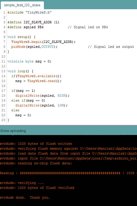
I wanted my master (the board with the RGB led) communicate with the slave (the board with the photodetector) ask for the value of the photodetector and turn on the green, red or blue led depending on the light. In exchange the master send to the slave a value (1,2, or 3) depending on the light. This is used by the slave to blink the signal led… I thought it was a smart way to make sure communication was happening and the code was working even if I could not see the master board…! But i will start with a simpler code ;-)
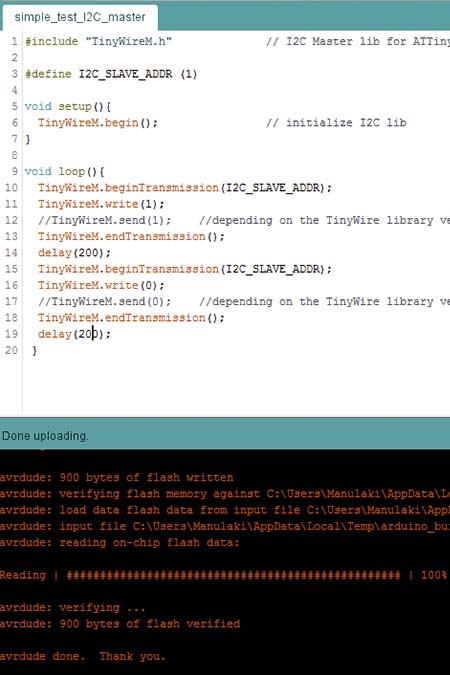
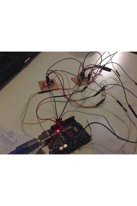
It works/ Master code
I tried once again with a cleared mind and with a simplier code. Actually i tried the first code that i used for the serial bus and it worked!!!
Conclusions//
The conclusion of this week is that communication should always be clear ;-)